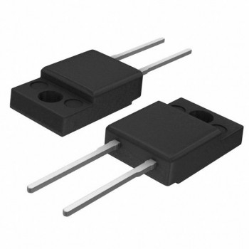
Zener diodes play a crucial role in various electronic circuits as voltage stabilizers and regulators, ensuring stable power supply and protecting sensitive components. As with any electronic component, correctly identifying the positive and negative poles of a Zener diode is paramount for proper function. The following article provides several methods to help you distinguish between the anode and cathode of a Zener diode.

1. Visual Inspection: Manufacturers often mark the diode's exterior with indicators to assist users in identifying the positive and negative poles. Common identifiers include ink markings, etchings, or indentations on the diode's casing. In some cases, the anode (positive) end might be marked with red ink, while the cathode (negative) end might be marked with black ink.
2. Pin Length: For certain types of Zener diodes, the pin length of the positive and negative poles might vary. Generally, the anode (positive) pin is longer, and the cathode (negative) pin is shorter. However, keep in mind that this rule is not always accurate, especially for used or repurposed components.
3. Multimeter Testing: A digital multimeter can provide a definitive method to distinguish between the anode and cathode of a Zener diode. Set the multimeter to diode testing mode. Connect the red (positive) probe to the suspected anode and the black (negative) probe to the suspected cathode. A displayed value greater than zero and within a typical diode voltage drop range (e.g., 0.5V to 0.8V) indicates that the probes are correctly connected to the anode and cathode.
With these techniques, you can effectively identify the positive and negative poles of a Zener diode. Ensuring the correct polarity during installation is essential for maintaining a stable, well-performing circuit. When working with electronic components, always adhere to safety guidelines to minimize the risk of electric shocks or potential component damage.
Diode related articles:
How Diodes Work and Selection Guide
Diode Hot Products:

