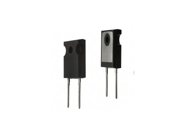
The Schottky diode is a special type of diode that has a very low voltage drop and fast switching speed. This means it can switch quickly at high frequencies and enable efficient power management at low voltages. So, do you really use Schottky diodes? Compared with other diodes, what is special about Schottky diodes? Next, let’s highlight the key points together!

1. In general design, we have to leave a certain margin. For example, VR only uses less than 80% of its rated value (can be controlled to less than 50% under special circumstances), and IF uses less than 40% of its rated value. In the single-ended flyback (FLY-BACK) switching power supply, it is assumed that the input voltage Vi(max)=350VDC, the output voltage Vo=5V, and the current Io=1A. According to the calculation formula, the reverse voltage VR and forward current IF of the rectifier diode are required to meet the following conditions:
VR≥2VI×NS/NP
IF≥2IO/(1-θmax)
in:
NS/NP is the transformer secondary and primary turns ratio
θmax is the maximum duty cycle
Assume, NS/NP=1/70, θmax=0.35, then VR≥2×350/20=10.7(V), IF≥2×1/(1-0.35)=3(A). In this way, we can refer to products using MDD Schottky SS34B (SMB package 3A40V). However, the heat dissipation of chip devices is usually limited, and the current of rectifier devices is greatly affected by temperature. As the chip junction temperature rises, the current capability decreases, so the temperature issue must be considered when selecting. Therefore, SS34 is not suitable for actual selection. In type applications, there is a risk of current attenuation due to temperature rise. At the same time, if the load is a capacitive load, there will also be mutual inductance superposition between the transformers. Therefore, sufficient margin must be left in the selection of current and voltage to ensure the normal performance of the product. To operate and extend the service life of the product, it is recommended to choose SS56B (SMB package 5A60V) or SS56C (SMC package 5A60V) products.
Note: For the heat dissipation and installation form of power Schottky diodes, it is necessary to understand the temperature requirements of the product, the environment in which it is used, the heat dissipation method adopted, etc. The power device should be installed in a location that is easy to ventilate and heat dissipate to improve the reliability of the product. Thermal silicone grease should be added between the plug-in type Schottky such as TO-220 and TO-220F and the radiator to ensure good contact between the tube and the radiator. For patch-packaged products, try to increase the area and thickness of the copper foil at the welding location so that the product can better dissipate heat, reduce the temperature of the power device when it is working, and improve product reliability.
2. Correctly select the RC compensation network of Schottky diode - RC buffer. Since the leakage inductance of the high-frequency transformer and the junction capacitance of the tube form a resonant circuit when turned off, it can cause instantaneous overvoltage oscillation. Therefore, it is necessary to set up an RC buffer in the power output to protect the safety of the tube. In addition, the RC network can also reduce output noise, reduce heat consumption of the tube, and improve product efficiency and reliability.
The principle of buffer selection is to make the buffer effective while minimizing losses. Below is the reference formula.
R=√(Li/Cj)/n where: Li is the leakage inductance of the transformer (μH)
CJ is the junction capacitance (PF) of the tube
N is the primary and secondary turns ratio (NP/NS)
The capacitance C can be arbitrarily selected from 0.01 to 0.1μF, and the specific value can be determined experimentally.
For Vo=5V, optional R=5.1Ω, 0.5W, C=0.01μF
Tubes with a small IR have low heat consumption, so under the same circumstances, you can choose a tube with a small IR.
When designing the PCB, keep tubes and heat sinks as far away from heat-sensitive components as electrolytic capacitors. to increase the life of the product.
The pad of the welded pipe must be large enough and the welding must be firm to avoid desoldering due to thermal stress.
Once a Schottky diode is selected, it must undergo simulation experiments to measure its temperature rise and operating waveform under the worst conditions of product input and output to confirm that each indicator does not exceed its limit parameters.

