I. Introduction
Because it is necessary to update the original circuit board based on the old controller chip design, today we will use this STM32F373 microcontroller to design a signal acquisition and control circuit board. We will design and produce it first, and then conduct software debugging.
2. Circuit design
The core of the control circuit board is STM32F373, which uses its ADC and DAC to interact with external control objects. The external analog signal is input to the 16-bit ADC of F373 after being filtered by resistance and capacitance. The 12-bit DAC it outputs controls the external circuit. In addition, it communicates with the host computer through the USB interface. As an experimental circuit board, all wires should be laid on the TOP LAYER as much as possible. This will make it easier to obtain the test circuit board later through the one-minute board production method.
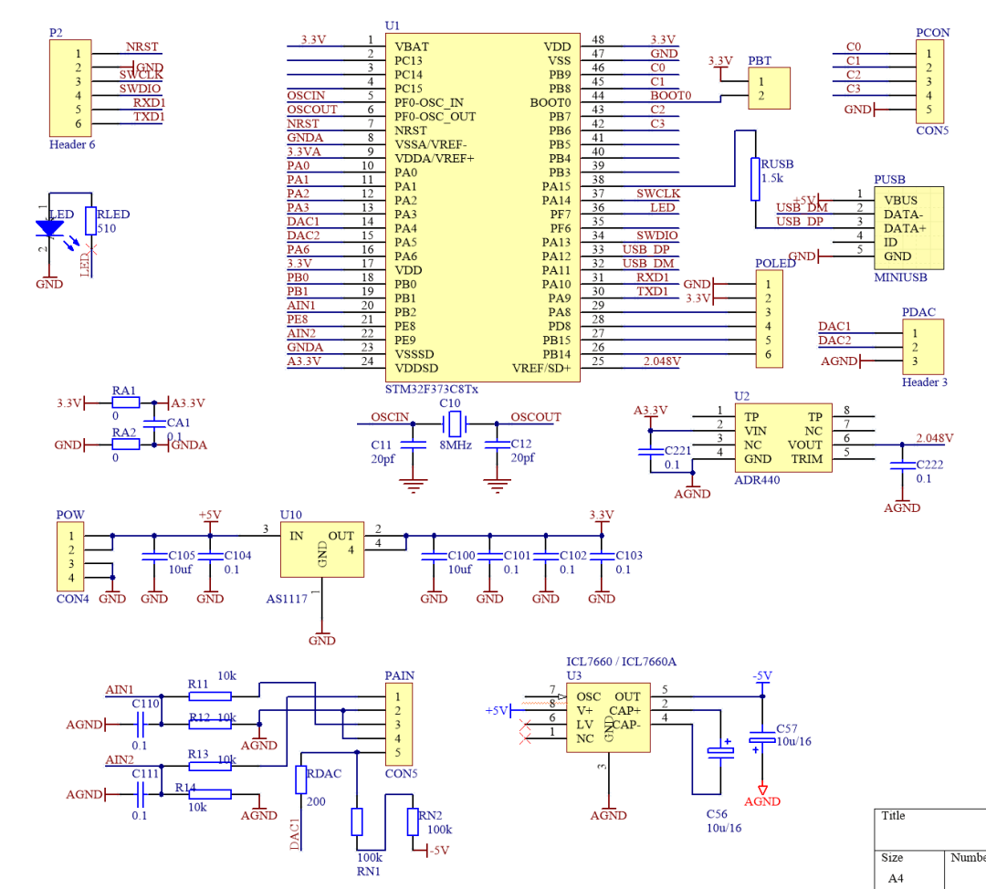
▲ Figure 1.2.1 Experimental circuit schematic diagram
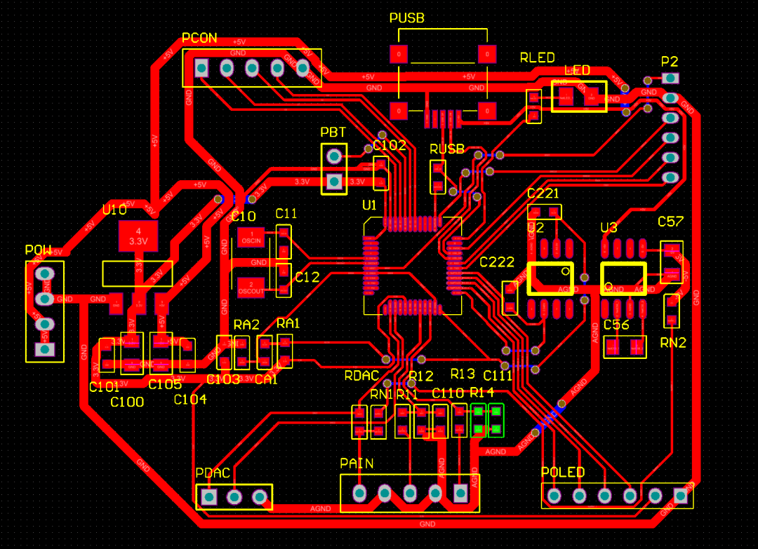
▲ Figure 1.2.2 Experimental circuit PCB
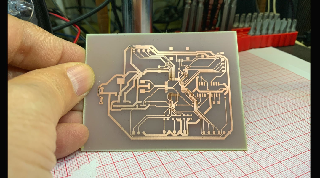
One minute later, the test circuit board was obtained, and the circuit board was made perfectly. These very close vias are where the 0 ohm flying leads will be used later.
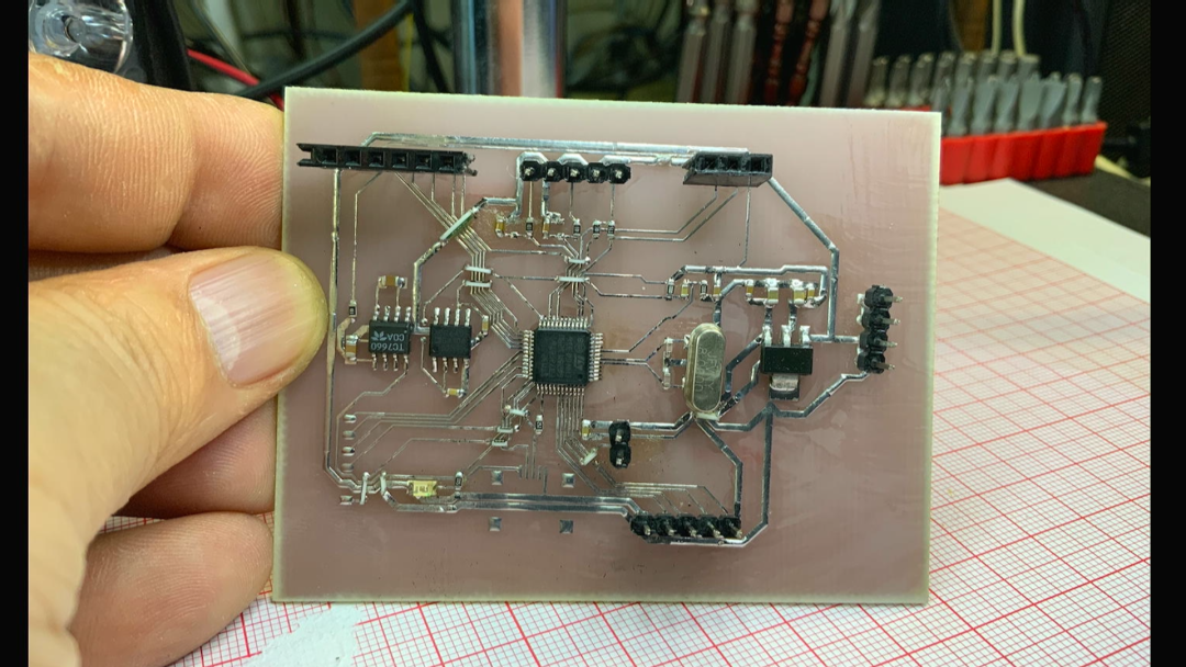
3. Welding circuit
Tin the circuit board first to facilitate subsequent soldering. After tin is applied, defects on the circuit board can be easily detected. Soldering the circuit board, of course, requires careful inspection of the core TSOP48 packaged F373 microcontroller. There seems to be a flying wire that is not welded, and will be repaired later. On this circuit board, except for the Mini USB interface, everything else is soldered. Solder the USB socket below. Use solder paste for soldering. Heating, this process requires patience. There is a bit too much solder paste on the pins, causing adjacent pins to stick together. Use a soldering iron to remove excess solder later.
Summarize
This article records the production of a signal acquisition and control circuit board based on STM32F373. Using the one-minute board-making method, the circuit board was quickly produced. Let's start the debugging process of it.