Implementing 0~10V output circuits is usually used to control various equipment, such as driving motors, adjusting valves, controlling lights, etc. The following are several common solutions for microcontrollers to implement 0~10V output circuits:
1. Digital to Analog Converter (DAC): Using a DAC chip is one of the most common and accurate methods. The DAC chip converts the digital signal into an analog voltage output. The microcontroller communicates with the DAC chip through SPI, I2C and other communication protocols, sending digital signals, and the DAC chip outputs the corresponding analog voltage. 8-bit, 10-bit, 12-bit or higher resolution DAC chips can be selected to meet accuracy and cost requirements.
For example, our most common microcontroller power supply system is: 0 ~ 3.3V. Then we can amplify 0 ~ 3.3 V by 3 times to achieve an output of 0 ~ 10V. Here we use a non-inverting proportional operational amplifier circuit, as shown below:
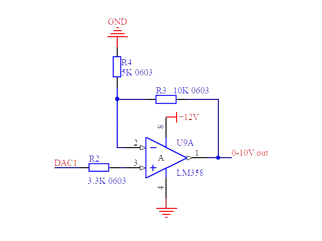
DAC1 is the DAC output of the microcontroller, 0 ~ 3.3V, amplified 3 times.
R2 is chosen to be 3.3K because of the symmetry of the op amp. Choose a resistance equal to the parallel resistors of R4 and R3.
2. Pulse width modulation (PWM) + filter circuit: Use the PWM output of the microcontroller to simulate the voltage value by controlling the duty cycle. The PWM signal is then filtered through a low-pass filter circuit to obtain a stable analog voltage output. This method is low-cost, but has low accuracy. The accuracy and stability of the output voltage are affected by the PWM resolution and filter circuit.
3. R-2R network: The R-2R network is a digital-to-analog conversion circuit consisting of a series of resistors that can convert digital input into an analog voltage output. The microcontroller generates corresponding voltages by controlling the IO port to output different levels (0 or VCC). The advantages of the R-2R network are simplicity and low cost, but the accuracy may not be as high as the DAC chip.
4. RC integrating circuit: Use the RC integrating circuit to convert the digital output signal of the microcontroller into an analog voltage. By changing the time constant of the RC circuit, the range and accuracy of the output voltage can be adjusted. This method is simple and low-cost, but its accuracy is usually not high and is greatly affected by temperature and circuit parameters.
5. Operational amplifier (Op-Amp) feedback circuit: Use an operational amplifier to build a feedback circuit to convert the digital output of the microcontroller into an analog voltage output. You can use an inverting amplifier or a non-inverting amplifier circuit to achieve an output of 0~10V by adjusting the feedback resistor and input voltage. This method has high accuracy, but the circuit complexity and cost are high.
6. Digital potentiometer: Use a digital potentiometer as a voltage output device. The microcontroller controls the resistance of the digital potentiometer through communication protocols such as I2C or SPI to adjust the output voltage. This method is simple and easy to implement, but is usually not as accurate as a DAC chip.
7. Integrated analog output unit: Some microcontrollers have integrated analog output units that can directly generate analog voltage output. By configuring the register or using a specific API, an output of 0~10V can be achieved. This method is simple and convenient, but it is limited by the microcontroller model and performance.
The above are some common solutions for microcontrollers to implement 0~10V output circuits. Choosing the right solution should be based on factors such as application requirements, cost, accuracy, and system complexity.