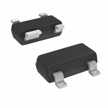
Among various power devices, MOS tubes may face a variety of faults, including overvoltage, overcurrent, overheating, etc.TOPCHIP ELECTRONICS, a spot supplier of electronic components, will introduce in depth the causes of MOS tube failure and propose corresponding protective measures.

1. Overvoltage
MOS tubes have very little tolerance for overvoltage, and slightly exceeding the rated voltage can cause equipment damage. To prevent overvoltage, the rated voltage should be considered conservatively and care should be taken to suppress voltage spikes or ringing.
2. Long-term current overload
High current for a long time will generate a large amount of heat dissipation in the MOS tube, leading to overheating damage. To ensure good heat dissipation, high load current can be shared by directly connecting multiple MOS tubes in parallel.
3. Transient current overload
A brief and large current overload may gradually damage the MOS tube, but the temperature of the MOS tube may not increase significantly before the failure occurs. Such situations can reduce the chance of breakdown by increasing dead time.
MOS tube failure analysis and protective measures
4.Breakdown (cross conduction)
Overlapping control signals of two opposite MOS tubes may cause both to be turned on at the same time, causing a power supply short circuit. Setting dead time minimizes the chance of breakdown.
5. No freewheeling current path
When the inductive load switches current, ensure that a freewheeling path is provided, usually by connecting a reverse freewheeling diode in parallel.
6. Slow reverse recovery of MOS tube body diode
High-Q resonant circuits may cause problems with MOS transistor body diodes when switching. Mitigated by adding diodes, such as a Schottky diode in series with the source and a fast recovery diode in parallel.
7. Excessive gate drive
Gate driving higher than the rated voltage may damage the gate insulation layer, ensuring that the gate signal does not exceed the maximum allowable voltage.
8. Insufficient gate drive (not fully turned on)
Make sure the MOS tube is hard turned on to reduce power consumption during conduction.
9. Slow switching transitions
Switch between states as quickly as possible to reduce power consumption during switching.
10.Spurious oscillation
Minimize stray inductance and capacitance around the MOS tube, and use a low-impedance gate drive circuit to prevent signal coupling.
11. "Miller" effect
Use low-impedance gate drivers to minimize the Miller effect and ensure the gate voltage is clamped to safe levels.
12. Radiated interference to the controller
Make sure the controller is placed in a shielded enclosure with power and control circuits separated.
13. Conducted interference to the controller
By reducing conducted interference through decoupling and neutral grounding, the use of transformer coupling is very effective in preventing electrical noise from being conducted back to the controller.
14. Static electricity damage
Use anti-static treatment when installing MOS tubes to prevent damage to the gate oxide layer.
15. High standing wave ratio
In pulsed systems, consider VSWR to ensure that the transmission line and load are matched to reduce problems caused by reflections and impedance discontinuities.
By understanding the causes of these failures, engineers can take corresponding protective measures to improve the stability and reliability of MOS tubes.

