The potential for high voltages is a constant concern in industrial applications. Finding ways to protect has been and will continue to be an important task for developers. The design techniques described in this article illustrate how developers can achieve this goal using Over-The-Top® (OTT) amplifiers.
Even industrial applications sometimes encounter voltages higher than the system power supply. The potential, although not as high as in applications such as automotive electronics, is often higher than the typical system voltage. Some system voltages may even be too high for many op amps. This brings huge challenges to the analog front end (AFE). For example, a higher voltage causes a typical amplifier's internal input diode to conduct. The longer this state exists, the greater the likelihood of malfunction or even failure. Developers can take appropriate precautions, such as external protection circuits using additional diodes or resistors. However, these additional components take up space on the circuit board and have drawbacks such as leakage current, increased input capacitance, and noise. Therefore, integrated IC solutions using Over-The-Top technology are a very good choice.
How Over-The-Top works
To simplify the explanation, take a look at the internals of the latest generation ADA4098-1 or ADA4099-1. These OTT op amps each have two input stages. The first stage is a common-emitter differential amplification stage consisting of PNP transistors and is suitable for input signals from a negative supply (–VS) to about 1.25 V lower than the positive supply (+VS). The second stage is a common-base input stage composed of more PNP transistors, suitable for common-mode voltages of the input signal starting from +VS – 1.25 V or higher. An example of the internal circuit is shown in Figure 1. The first stage is designed using transistors Q1 and Q2, while the second stage is designed using transistors Q3 to Q6.
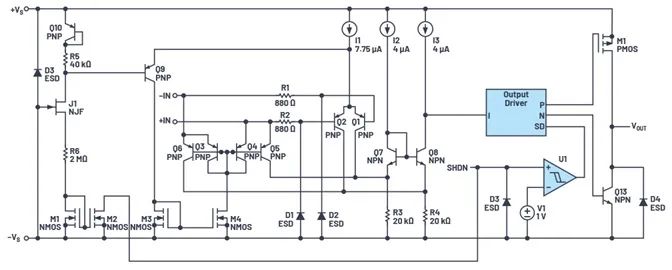
Figure 1. Simplified representation of the internal structure (taken from the latest generation ADA4098-1).
Therefore, these input stages provide two different but complementary operating ranges. The offset voltages of the two input stages are tightly trimmed and are given in the data sheet.
When the input common-mode voltage approaches +VS, the second stage is activated and the op amp is in Over-The-Top mode. This can be an overvoltage condition in various applications. For example, for high-side current measurements, the input voltage may momentarily exceed the system supply potential due to parasitics or load-related effects. Typical amplifiers allow input signal voltages up to the supply voltage rails. If the input is far outside this range, the internal diode will usually conduct and a large amount of current will flow through it. Depending on the signal voltage and current, these spikes can momentarily interrupt the operation of the amplifier and, in the worst case, even cause the integrated circuit to fail.
Unlike typical op amps, OTT amplifiers can tolerate differential input voltages up to 80 V when such problems occur. In this state, the output level saturates to the positive supply voltage (+VS). In this state, the output is still capable of sinking or outputting the nominal limit current in the data sheet. Once the input returns to the normal operating range (–VS to +VS), the output level returns to the normal linear range without compromising or degrading DC accuracy. The situation is similar for common-mode voltages up to 70 V.
Application examples and tips for amplifiers with OTT technology
Figure 2 provides some current measurement examples. The ADA4098-1 is the lower power version, while the ADA4099-1 has higher bandwidth and higher voltage rise rate.
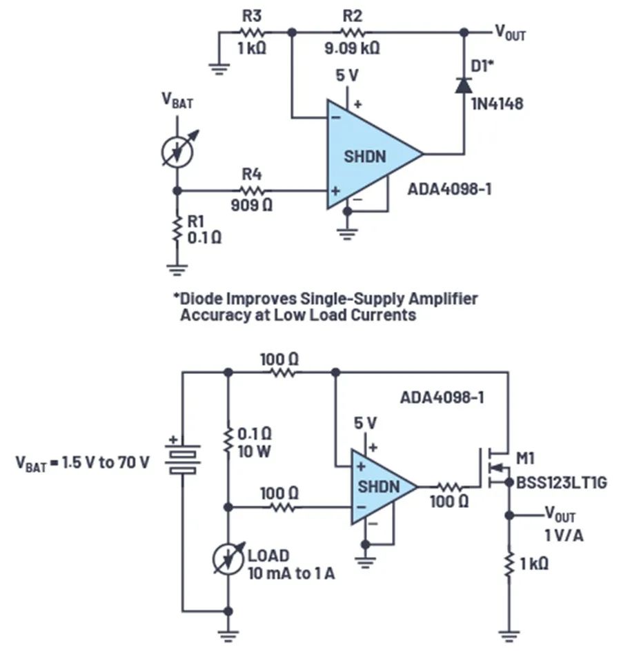
Figure 2. Current measurement example using the ADA4098-1.
In low-side measurements, the gain comes from resistors R2 and R3. Diode D1 improves measurement accuracy in single-supply systems at low load currents.
In high-side current measurements, the 1 kΩ Vout terminal connected to ground and the 100 Ω (top connection) resistor at the non-inverting terminal of the op amp determine the gain (the shunt ratio of 0.1Ω to 100Ω determines the gain, and the 1k resistor converts the current to voltage) . Resistors at the amplifier input provide functions such as filtering. In this case, a 1% accuracy resistor would be a better choice. The op amp's input bias current may affect the voltage drop across these resistors, and a small tolerance like 1% will help minimize the voltage drop range here.
The output of the ADA4098-1 has rail-to-rail swing (within 45 mV minus each supply rail) at no load. The output can source 24 mA and sink 35 mA. The amplifier has an internal compensation mechanism and can drive a load capacitance of 200 pF (minimum). A 50 Ω series resistor can be inserted between the output and higher capacitive loads to extend the amplifier's capacitive load drive capabilities.
If the output VOUT drives a circuit with a lower potential, and that load circuit has its own voltage rail's protection diode, it makes sense to put a resistor at VOUT. This will limit the current that can flow to the load circuit.
The ADA4098-1 has a dedicated SHDN pin that, when asserted high, puts the amplifier into a very low-power shutdown state. A logic high level is defined as the reference –VS potential, a voltage ≥1.5 V plus –VS applied to the SHDN pin. The VOUT pin is then in a high impedance state. As an alternative, the amplifier can be put into a low power state by removing the positive supply. In both shutdown modes, OTT remains active and can apply voltages up to more than 70 V above –VS to the input pins.
In addition to current or power measurements, other uses for OTT amplifiers are in sensor front ends or in 4 mA to 20 mA current loops. Detailed information, further application examples and calculations can be found in the data sheet.
This article explains how Over-The-Top amplifiers provide overvoltage protection. With smart and sophisticated internal circuitry, Over-The-Top amplifiers deliver both robustness and accuracy.
ADI's fifth-generation OTT amplifier brings the latest overvoltage protection technology from the laboratory to actual circuit design. OTT op amps such as the ADA4098-1 and ADA4099-1 not only tolerate voltages well above the supply rails, but also achieve lower offset error and noise values.